

seismic performance of various geocell earth-retention systerm(2) http://www.kreennewmaterials.com Taian kreen newmaterials co.,ltd Time updated :2016-06-27
Shake table testing program
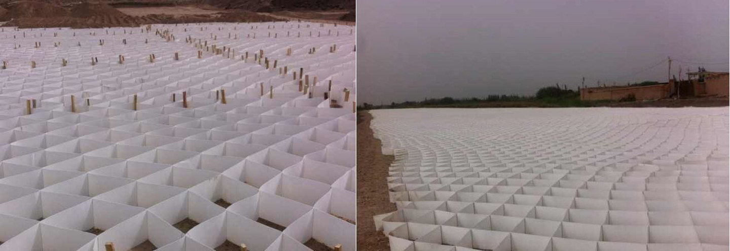
This shake table is located at the Japan National Research Institute of Agricultural Engineering, Tsukuba City, and it can excite gross maximum payload of 500kN to vertical and/or horizontal acceleration of 1g; maximum accelerations for lighter payloads can be larger than 1g. The metal testing box containing the geocell retention systems was 2m wide, 6m long, and 3m tall. To minimize reflection of waves from the side and rear of the metal box, expanded polystyrene (EPS) boards, 5cm thick, were placed against the testing box walls. To reduce friction with the sidewalls, greased plastic sheeting was placed against the EPS.
In all tests, an amplified time record of the 1995 Kobe earthquake was applied to the shake table. The Kobe record used had horizontal PGA of 0.59g and a vertical PGA of 0.34g. The peak horizontal and vertical accelerations did not occur simultaneously. Table 1 shows the applied peak accelerations in four different tests.
Table 1 | Figure courtesy of the author.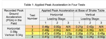
There were either two or three loading stages.
In the first loading stage, the Kobe record was attenuated in an attempt to verify whether excessive movements occurred. An hour later the second loading stage was applied, amplifying the Kobe record. In Tests 3 and 4, a third excitation was applied, this time reaching the capacity of the shake table. The third stage nearly doubled the Kobe recorded acceleration. Stage 2 was aimed at developing an active wedge; it was hoped that the third stage would bring about collapse.
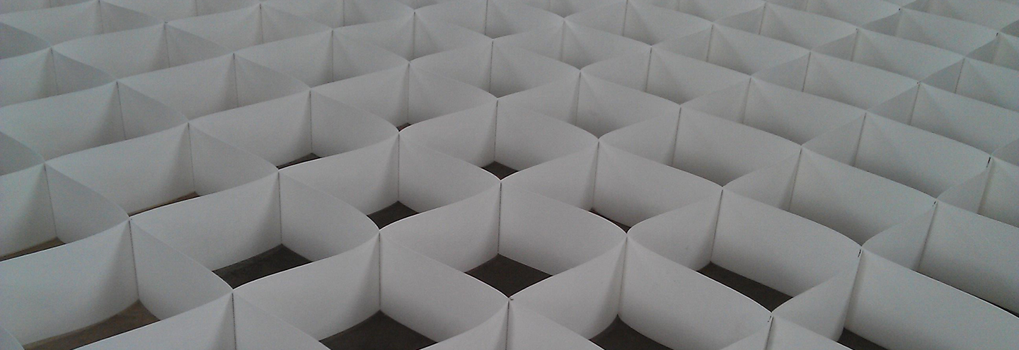
In Tests 1-3, the retention system was 2.8m high; in Test 4 it was 2.7m. All retention systems were constructed over a 0.2m-thick foundation soil. The geocells, resembling a honeycomb structure, were 0.2m high with internal aperture of approximately 0.21m by 0.21m. The average face inclination of the systems was 2(v):1(h). The top geocell layer was 2.52m long, much longer than all layers below. This top layer was infilled with compacted gravel. It was assumed that long top layer made of geocell would inhibit crack or even slip surface formation immediately below this layer. Indeed, tests indicated that while numerous small and shallow tension cracks initiated at the crest, none was observed immediately below the long top geocell layer in any of the tests, thus supporting the initial assumption.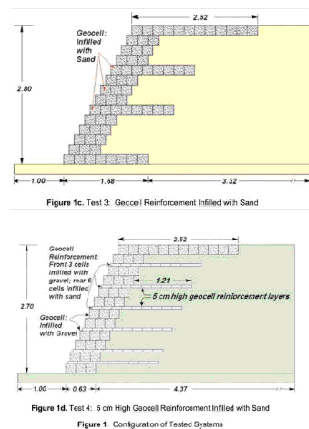
Figure 1 (a–d) shows the geocell layout in each of the four tests.
Figure 1a | Test 1: gravity wall with gravel infilled geocell. Figure courtesy of the author.
Figure 1b | Test 2: gravity wall with sand infilled geocell. Figure courtesy of the author.
Figure 1c | Test 3: geocell reinforcement infilled with sand. Figure courtesy of the author.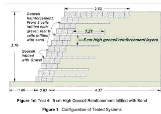
Figure 1d | Test 4: 5cm-high geocell reinforcement infilled with sand. Figure courtesy of the author.
Tests 1-2 represented flexible gravity walls and Tests 3-4 utilized geocell as reinforcement and facing. In terms of economics, the systems in Tests 3 and 4 are about the same. In Test 4 the layout of geocell resembled that of traditional geogrid reinforcement while still acting as 3-D element. Generally, the polyethylene geocell used in the tests cannot be used as reinforcement for sizeable structures since it has low long-term tensile strength. As tested, only sufficient short-term properties were needed to resist the seismic loading. However, the lessons should indicate the needed product improvements in developing Neoweb®, which is made of Neoloy®, as well as produce a simple design methodology.
The backfill soil behind the facing and in the 0.2m-thick foundation was fine uniform sand (Median Grain Size = 0.27mm; 0.35% passing sieve #200; Uniformity Coefficient = 2). The backfill was compacted to 90% of Standard Proctor at a moisture content of 16% yielding a dry unit weight of 13.5 kN/m3 or moist unit weight of 15.6 kN/m3. Compaction was done by a handheld vibratory compactor. Drained triaxial tests yielded peak strength of =38 degrees. Unit weight of the compacted gravel was 19.9 kN/m3.
Thin white seams of sand were placed every about 0.4m within the backfill material. Upon completion of each test, the backfill was carefully excavated to observe dislocations of these seams so that traces of slip surfaces could be identified. In addition, each test was comprehensively instrumented including pressure transducers, laser displacement gages, accelerometers, and strain gages (Ling et al, 2009).